Advanced : Wind Turbine
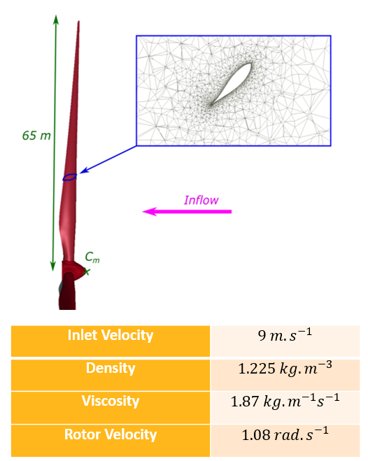
Sliding mesh is a technique that prevents excessive re-meshing in problems that involve rotating parts and is frequently involved in turbomachinery or for wind turbine simulations. The ICFD solver's capabilities have been extended in order to make the solve of such applications possible. This example features a wind turbine with prescribed rotation
https://www.dynaexamples.com/icfd/advanced-examples/windturb
https://www.dynaexamples.com/@@site-logo/LS-DYNA-Examples-Logo480x80.png
Advanced : Wind Turbine
Sliding mesh is a technique that prevents excessive re-meshing in problems that involve rotating parts and is frequently involved in turbomachinery or for wind turbine simulations. The ICFD solver's capabilities have been extended in order to make the solve of such applications possible. This example features a wind turbine with prescribed rotation
*KEYWORD
*TITLE
*DATABASE_BINARY_D3PLOT
*DEFINE_CURVE_TITLE
*ICFD_BOUNDARY_FREESLIP
*ICFD_BOUNDARY_PERIODIC
*ICFD_BOUNDARY_NONSLIP
*ICFD_BOUNDARY_PRESCRIBED_PRE
*ICFD_BOUNDARY_PRESCRIBED_VEL
*ICFD_CONTROL_IMPOSED_MOVE
*ICFD_CONTROL_MESH
*ICFD_CONTROL_OUTPUT
*ICFD_CONTROL_TIME
*ICFD_CONTROL_TURBULENCE
*ICFD_DATABASE_DRAG
*ICFD_MAT
*ICFD_PART
*ICFD_PART_VOL
*ICFD_SECTION
*INCLUDE
*MESH_BL
*MESH_SURFACE_ELEMENT
*MESH_SURFACE_NODE
*MESH_VOLUME
*END
$-----------------------------------------------------------------------------
$
$ Example provided by Iñaki (LST-Ansys)
$
$
$X------------------------------------------------------------------------------
$X
$X 1. Run file as is.
$X    Requires LS-DYNA MPP R12.0.0 (or higher) with double precision
$X
$X------------------------------------------------------------------------------
$# UNITS: (S.I)
$X------------------------------------------------------------------------------
$X
*KEYWORD
*INCLUDE
mesh_blade_slide_diff.k
*PARAMETER
$--- Fluid
R  v_inlet    9
Rrho_fluid    1.225
R mu_fluid   1.87e-5
R dt_fluid    5.0e-5
R   turb_I      0.07
R dt_out         0.1
R total_t     25.002
R   angle     120.0
$
$---- Rotor
$
R    omega    1.08
$
*DATABASE_BINARY_D3PLOT
$#      dt      lcdt      beam     npltc    psetid
   &dt_out
*ICFD_CONTROL_TIME
$#     ttm        dt       cfl    lcidsf     dtmin     dtmax    dtinit    tdeath
$  &total_t        0.       2.0         0 &dt_fluid    1.0e-3       0.0       0.0
&total_t,1.e-3
*ICFD_CONTROL_MESH
1.8
$----------------------------------------------------------------------------------
*ICFD_CONTROL_OUTPUT
$#    msgl
         4
$---+----1----+----2----+----3----+----4----+----5----+----6----+----7----+----8
*ICFD_CONTROL_TURBULENCE
         2
$ ----------------- Control Sliding --------------------------------------------
*ICFD_CONTROL_IMPOSED_MOVE
40
100
12
*ICFD_CONTROL_IMPOSED_MOVE
1
100
12
*ICFD_CONTROL_IMPOSED_MOVE
11
100
12
*ICFD_CONTROL_IMPOSED_MOVE
12
100
12
*ICFD_CONTROL_IMPOSED_MOVE
13
100
12
*ICFD_CONTROL_IMPOSED_MOVE
3
100
12
*DEFINE_CURVE
$#    lcid      sidr       sfa       sfo      offa      offo    dattyp     lcint
         1         0       1.0       1.0       0.0       0.0         0         0
$#                a1                  o1
                 0.0                 1.0
             10000.0                 1.0
*DEFINE_CURVE
$#    lcid      sidr       sfa       sfo      offa      offo    dattyp     lcint
         2         0       1.0       1.0       0.0       0.0         0         0
$#                a1                  o1
                 0.0                 0.0
             10000.0                 0.0
*DEFINE_CURVE
$#    lcid      sidr       sfa       sfo      offa      offo    dattyp     lcint
         3         0       1.0   &turb_I       0.0       0.0         0         0
$#                a1                  o1
                 0.0                 1.0
             10000.0                 1.0
*ICFD_BOUNDARY_NONSLIP
$#     pid
         1
         8
        11
        12
        13
*ICFD_BOUNDARY_FREESLIP
$#     pid
         5
*ICFD_BOUNDARY_PERIODIC
$# pidmast   pertype   pidslav                 axe      ptid     angle
         3         3         4
*ICFD_BOUNDARY_PRESCRIBED_VEL
$#     pid       dof       vad      lcid        sf       vid     death     birth
        10         4         1        21       1.0         01.00000E28       0.0
*DEFINE_CURVE
$#    lcid      sidr       sfa       sfo      offa      offo    dattyp     lcint
        21         0       1.0  &v_inlet       0.0       0.0         0         0
$#                a1                  o1
                 0.0                 1.0
             10000.0                 1.0
*DEFINE_FUNCTION
20,x-velo
f(y,z)=-4.1977e14*(y**2+(z-0.294)**2)**3+5.5e12*sqrt(y**2+(z-0.294)**2)**5
-2.65e10*(y**2+(z-0.294)**2)**2+5.64e7*sqrt(y**2+(z-0.294)**2)**3
-5.86e4*(y**2+(z-0.294)**2)+2.365*sqrt(y**2+(z-0.294)**2)+1.157
*ICFD_BOUNDARY_PRESCRIBED_PRE
$#     pid      lcid        sf     death     birth
         9         2       1.01.00000E28       0.0
*ICFD_MAT
$#     mid       flg        ro       vis        st
         1         1&rho_fluid &mu_fluid       0.0
*ICFD_PART_TITLE
inlet
$#     pid     secid       mid
         9         1         1
*ICFD_PART_TITLE
outlet
$#     pid     secid       mid
        10         1         1
*ICFD_PART_TITLE
perioslv
$#     pid     secid       mid
         4         1         1
*ICFD_PART_TITLE
roof
$#     pid     secid       mid
         5         1         1
*ICFD_PART_TITLE
size
$#     pid     secid       mid
         3         1         1
*ICFD_PART_TITLE
rotor
$#     pid     secid       mid
         1         1         1
*ICFD_PART_TITLE
blade1
$#     pid     secid       mid
        11         1         1
*ICFD_PART_TITLE
blade2
$#     pid     secid       mid
        12         1         1
*ICFD_PART_TITLE
blade3
$#     pid     secid       mid
        13         1         1
*ICFD_PART_TITLE
motor
$#     pid     secid       mid
         8         1         1
$*icfd_part
$20,1,1
*ICFD_PART_VOL
40,1,1
1,3,11,12,13
*ICFD_PART_vol
$#     pid     secid       mid
        30         1         1
4,5,8,9,10
*ICFD_SECTION
$#     sid
         1
*DEFINE_CURVE_TITLE
Rotation velocity
$#    lcid      sidr       sfa       sfo      offa      offo    dattyp
       100                        &omega
$#                a1                  o1
                 0.0                 0.0
                 0.2                -1.0
                   4                -1.0
               100.0                -1.0
*DEFINE_CURVE_TITLE
Rotation velocity
$#    lcid      sidr       sfa       sfo      offa      offo    dattyp
       101
$#                a1                  o1
                 0.0                 0.0
                 0.2                 1.0
                   4                 1.0
               100.0                 1.0
*ICFD_DATABASE_DRAG
         1
*ICFD_DATABASE_DRAG
        11
*ICFD_DATABASE_DRAG
        12
*ICFD_DATABASE_DRAG
        13
$*icfd_define_noninertial
$0.,0.,&omega,68.,12,9.00,101,1
*icfd_define_point
12,0,0,-8.6
$-----------------------------MESH-----------------------------
*MESH_VOLUME
$#   volid
        15
$#    pid1      pid2      pid3      pid4      pid5      pid6      pid7      pid8
4,5,8,9,10
*MESH_VOLUME
16
1,3,11,12,13
*MESH_BL
1,2
*MESH_BL
11,2
*MESH_BL
12,2
*MESH_BL
13,2
*MESH_BL
8,1
$*MESH_BL
$$#     pid     nelth      blth      blfe      blst
$         1         3      1.25      0.01         3
$*MESH_BL
$$#     pid     nelth
$         8         3      1.25      0.01         3
$*MESH_SIZE_SHAPE
$$#   sname
$       box
$$#   msize     pminx     pminy     pminz     pmaxx     pmaxy     pmaxz
$   0.00035       0.0     -0.03     0.004     0.024    -0.026     0.009
*END
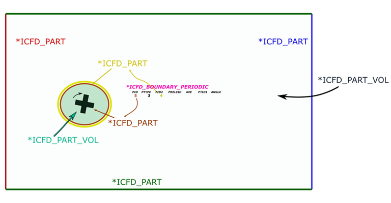
Sliding mesh sketch for setup :


Sliding mesh is a technique that prevents excessive re-meshing in problems that involve rotating parts and is frequently involved in turbomachinery or for wind turbine simulations. The ICFD solver's capabilities have been extended in order to make the solve of such applications possible. This example features a wind turbine with prescribed rotation.
