In typical Joule heating applications, current flows through a conductor which produces heat. The importance of Joule heating effects is dependent on the material’s electrical conductivity properties as well as on the amount of current flowing through it.
If the frequency of the current becomes high enough, typically in the range of MHz-GHz, molecular dipole rotation causes an additional heating term to appear and potentially become predominant: dielectric heating. Contrary to Joule heating, dielectric heating is not dependent on the material’s conductivity (the material can be nonconductor) but rather, on its dielectric properties (dielectric constant and dielectric losses).
To solve such problems, the complex frequency domain form of the electric field’s equation is adopted:

From the scalar potential solution, an electric field can be calculated from which two heating terms are extracted, Dielectric Heating Power (S.I unit in W) and Joule Heating Power (S.I unit in W):
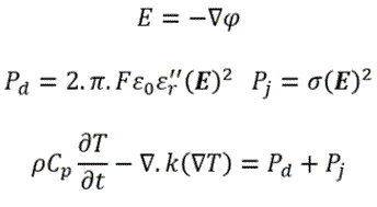
As typically done with other similar applications within LS-DYNA, those heating terms can automatically be passed to the thermal solver to solve coupled EM-thermal applications. In turn, the thermal solver temperature results can be used to update the dielectric constants, electrical conductivities, and dielectric losses if temperature dependent laws are defined (don't forget to periodically update your EM FEM matrices if that is the case !) . It is important to note that contrarily to pure resistive heating applications, the conductivity of the material needn’t be present, if the material is a nonconductor and only possesses dielectric properties.
The following boundary conditions and contacts are available for the EM RF heating solver:
- Imposed Voltage (Dirichlet)
- Imposed Current (Neumann)
- Imposed Resistance (Robin)
- Imposed Impedance (Complex Robin)
- Imposed Power (non-linear Dirichlet)
- Periodic/Sliding
- Contact (constraint or penalty based)
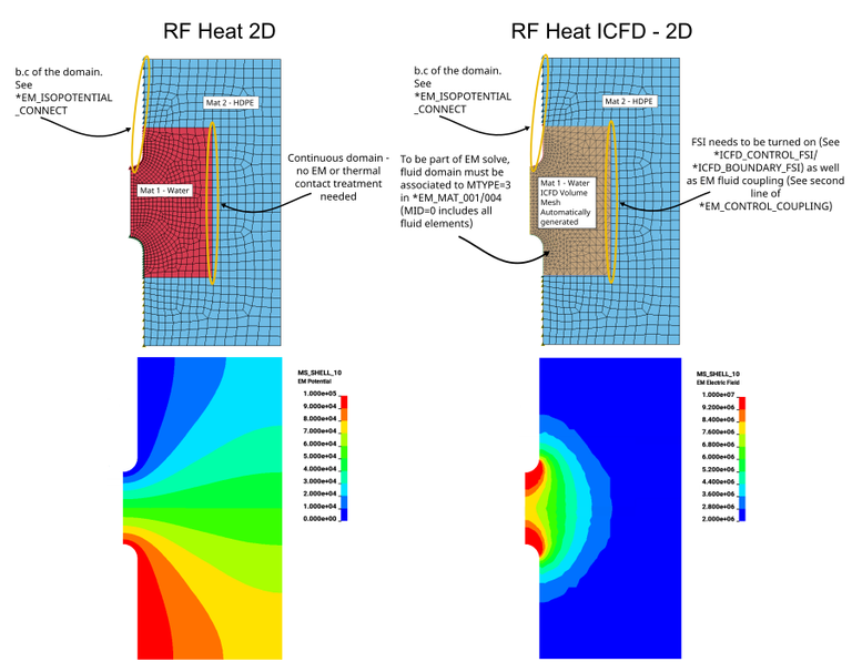
3D, 2D planar and 2D axisymmetric capabilities are present. The choice of dimension can be done in *EM_CONTROL. Finally, it is worth noting that coupling with the ICFD solver is present. The keywords *EM_MAT, *EM_ISOPOTENTIAL_CONNECT as well as *EM_BOUNDARY_PRESCRIBED allow the definition of dielectric properties and boundary conditions on the solid as well as ICFD domain. The dielectric domains can be made continuous between the fluid and the structure by using the keywords *ICFD_BOUNDARY_FSI and the appropriate option in *EM_CONTROL_COUPLING (Extra constraints between the fluid domain dofs and the structure dofs will be added to the system).
This first example is a simple 2D input. Two versions are presented, one set up models the water domain as a classic Lagrangian solid, the other approach uses the ICFD solver (even if no flow is present) :
rfheat_2d.zip
rfheat_2dicfd.zip
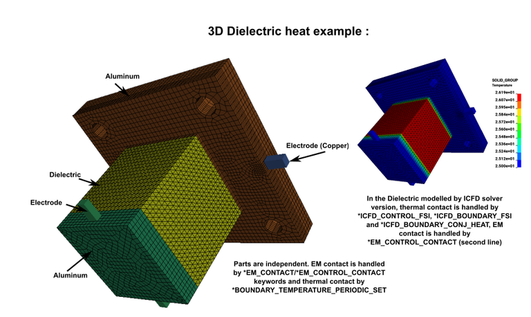
This example features a 3D problem where a dielectric material is contained between two aluminum blocks and heated by Electrodes. Two versions of the same problem are again presented. One modelling the dielectric material as a Lagrangian solid, the other as a ICFD Volume :
dielec_heat3d.zip
dielec_heat3d_icfd.zip
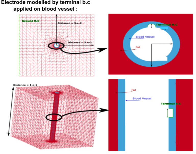
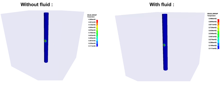
The following example is a typical medical industry application. An electrode is placed between a blood vessel and the surrounding tissue and a voltage is applied. Two configurations are studied. One without the thermal effect of the blood i.e a pure EM-thermal application :
rfheat_electrode.zip
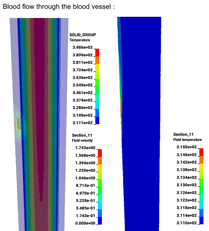
The second configuration adds the influence of the blood flow modelled with the ICFD solver (only the conjugate heat aspect, the blood flow is not part of the dielectric analysis). The problem then becomes a coupled CFD-EM-thermal simulation. The decrease in maximum temperature compared to the case without the blood flow can be analyzed.
rfheat_electrode_icfd.zip


