Tutorial Battery modelling
Battery modeling has been introduced in the EM solver in order to simulate battery cells under normal use conditions as well as during abusive scenarios where the battery cells are damaged and shorts can occur. The thinness of the different components of a unit cell (anode/cathode, separator, current collectors) makes battery modeling a challenge for each of the different physics involved (EM, mechanical, thermal) especially in impact and short cut scenarios. On the EM side, the challenge will consist in modeling the chemical reaction of ions moving in electrolyte. The EM solver uses the so called Randles circuits i.e equivalent circuit models to represent battery electrochemical reactions.
*EM_CONTROL
*EM_CONTROL_CONTACT
*EM_CONTROL_EROSION
*EM_CONTROL_SWITCH
*EM_CONTROL_TIMESTEP
*EM_ISOPOTENTIAL
*EM_ISOPOTENTIAL_CONNECT
*EM_ISOPOTENTIAL_ROGO
*EM_MAT_001
*EM_RANDLES_BATMAC
*EM_RANDLES_EXOTHERMIC_REACTION
*EM_RANDLES_MESHLESS
*EM_RANDLES_TSHELL
*EM_RANDLES_SHORT
*EM_RANDLES_SOLID
*EM_OUTPUT
*END
Figure showing the different scales of a battery pack components :
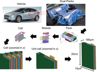
Figure showing the idea behind the distributed Randles circuits model :
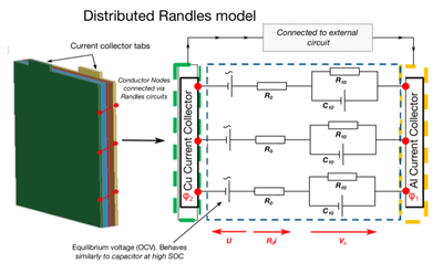
Figure showing the idea behind modelling the effects of an internal short :
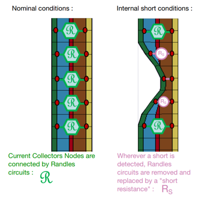
Figure showing the thick shell model : what the user sees versus what the EM solver internally rebuilds :

Figure showing the idea behind the batmac model. Rather than modelling all the internal layers, a few elements in the thickness are used and each node represents a region of 'macro effects' :
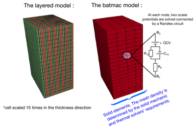
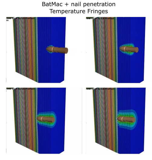
Figure showing a rigid nail penetrating and eroding multiple cells modeled using BatMac. The subsequent internal short causes a local temperature rise.
This fist set of examples introduces the user to the classic way of modelling a unit cell using solid elements and the keyword *EM_RANDLES_SOLID for modelling the Randles circuits. All the components of the cell are modeled by a distinct part in succession (watch for the elements' normals which must be correctly oriented) :
Positive Current Collector - Positive Electrode - Separator - Negative Electrode - Negative Current Collector
Once the current is flowing between the two current collectors, the connections to the tabs are done via the familiar *EM_ISOPOTENTIAL and *EM_ISOPOTENTIAL_CONNECT keywords.
Basic discharge admitting analytical solution : Basic
Adding thermal coupling : Basic_thermal
Adding the effect of SOCshift : Basic_socshift
An example of a simple internal short by adding the keyword *EM_RANDLES_SHORT : Basic_intshort
An example of how an exothermal reaction (thermal runaway) can be added with the keyword *EM_RANDLES_EXOTHERMIC_REACTION : Basic_exothermal
Using the solid element model, while convenient for studies of unit cell behavior, is not practical when applied to the scale of an entire battery cell, let alone module or pack due to time step restrictions and model size. The Thick shell Randles model has been introduced as an alternative. A complete cell can be modeled by using one composite thick shell. The EM will internally rebuilt the different layers for the EM solve based on the user’s input. The keyword is *EM_RANDLES_TSHELL and works in a similar fashion to *EM_RANDLES_SOLID (only the first line is different).
External short example : Tshell_extshort
Internal short example : Tshell_intshort
Cylindrical Battery model : Tshell_cylindrical
In the previous Tshell examples, the mechanics is solved on the composite Tshell, but an underlying solid mesh with all the layers still has to be built to solve the EM and the thermal. While better suited than the solid element model, this still implies very large meshes and hence simulation times when dealing with many cells, modules, packs or a full battery. This Battery Macro (BatMac) model allows simulating a cell with very few layers of elements (down to one). Two fields exist at each node of the mesh, representing the potential at the positive and negative current collectors. These 2 fields are connected by a Randles circuit at each node. It still is possible to include external and internal shorts. The internal shorts can be locally created depending on local values of different mechanical, thermal or EM parameters.
Simple Batmac models with Randles circuits order 0, 1, 2 as well as a user defined circuit example reproducing a Randles circuit order 2 : Batmac_circuits
Example showing how *DEFINE_TABLEs can be used to have Randles circuit parameters function of SOC and Temperature : Batmac_table
Batmac model with internal short : Batmac_intshort
Example of Cylindrical Cells with Batmac model : Batmac_cylinder
Example of a nail penetrating multiple cells modeled with Batmac model (Erosion triggers an internal short which, in turn causes a local temperature rise) : Batmac_nail
Finally a meshless model exists which allows to directly connect two isopotential to a Randles circuit via the introduction of the keyword EM_RANDLES_MESHLESS. This is suited in order to study the effects of the circuit parameters on a simple charge/discharge or even for some external short configurations where modelling the individual Randles circuits is not needed and where any thermal effect in the current collectors can be neglected.
Meshless model with external short : Meshless
