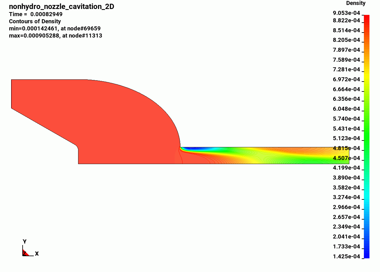
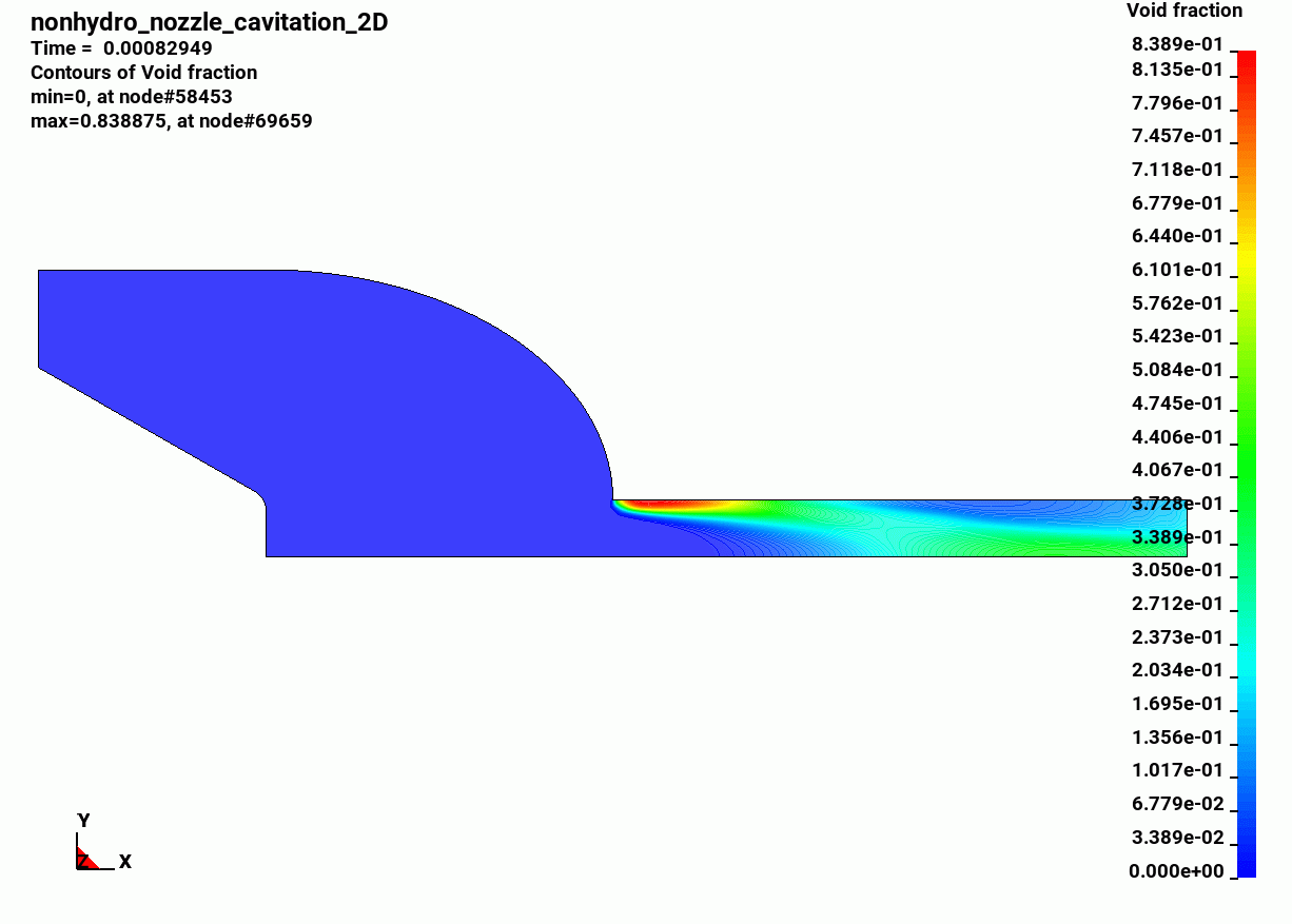
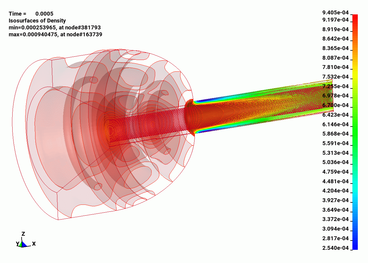
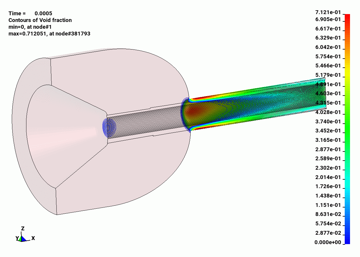
This example features both a 2D input deck and a 3D input deck. In the 2D cavitation problem, we test a cavitation model implemented in the dual CESE solver (Please note, this cavitation model has previously been implemented in the regular CESE solver). The cavitation model used is Schmidt’s homogeneous equilibrium model[1] (HEM), which is based on the acoustic speed of the mixture of liquid and vapor. This model is simple but contains the important characteristic information of cavitating flows. This cavitation model is very suitable for high-speed flows in small geometry, like diesel injection systems. In the 3D cavitation problem, the 2D cavitation in a non-hydro nozzle model is extended to a 3D cylinder shape non-hydro nozzle.
References:
[1] Schmidt, D.P.,Rutland, C. J., Corradini, M. L. (1999), “A Fully Compressible Two-Dimensional Model of Small, High Speed Cavitating Nozzles,” Atomization Sprays Technology 9: 255-276.
*DUALCESE_MODEL
*DUALCESE_CONTROL_SOLVER
*DUALCESE_CONTROL_TIMESTEP
*DUALCESE_CONTROL_LIMITER
*DUALCESE_INCLUDE_MODEL
*DUALCESE_BOUNDARY_PRESCRIBED_SEGMENT_SET
*DUALCESE_BOUNDARY_SOLID_WALL_SEGMENT_SET
*DUALCESE_INITIAL
*DUALCESE_PART
*DUALCESE_EOS_CAV_HOMOG_EQUILIB
*DUALCESE_D3PLOT
*CONTROL_TERMINATION
*DATABASE_BINARY_D3PLOT
*DATABASE_BINARY_D3DUMP
$================================================================================
*KEYWORD
$$$$$$$$$$$$$$$$$$$$$$$$$$$$$$$$$$$$$$$$$$$$$$$$$$$$$$$$$$$$$$$$$$$$$$$$$$$$$$$$
*DUALCESE_CONTROL_SOLVER
$ icese igeom iframe MixSelect
N-S 2D fixed cavi
*DUALCESE_CONTROL_TIMESTEP
$ iddt cfl dtint
1 0.9 0.0006
*DUALCESE_CONTROL_LIMITER
$ idlmt alfa beta epsr
0 2.0 1.0 .005
$
*DUALCESE_INCLUDE_MODEL
fluid_m2h.k
$$$$$$$$$$$$$$$$$$$$$$$$$$$$$$$$$$$$$$$$$$$$$$$$$$$$$$$$$$$$$$$$$$$$$$$$$$$$$$$$
$
$ Setup the boundary conditions for fluid
$
$ Inlet Prescribed BC (left)
$
*DUALCESE_BOUNDARY_PRESCRIBED_SEGMENT_SET
$ ssid
1
$ lcid_u lcid_v lcid_w lcid_d lcid_p lcid_t
-1 -1 -1 -1
$ sf_u sf_v sf_w sf_d sf_p sf_t
-1 -1 -1 -1
100 0.0 9.321e-4
*DUALCESE_BOUNDARY_PRESCRIBED_SEGMENT_SET
$ ssid
4
$ lcid_u lcid_v lcid_w lcid_d lcid_p lcid_t
-1 -1 -1 -1 -1
$ sf_u sf_v sf_w sf_d sf_p sf_t
1.0e+5
$
*DUALCESE_BOUNDARY_REFLECTIVE_SEGMENT_SET
$ ssid
3
$
$ Solid BC_3 (bottom)
$
*DUALCESE_BOUNDARY_SOLID_WALL_SEGMENT_SET
$ ssid
2
$
$$$$$$$$$$$$$$$$$$$$$$$$$$$$$$$$$$$$$$$$$$$$$$$$$$$$$$$$$$$$$$$$$$$$$$$$$$$$$$$$
$
$ Setup the initial conditions for fluid
$
*DUALCESE_INITIAL
$ uic vic wic rhoic pic tic
$ 0.0 0.0 0.0 8.8e-4
0.0 0.0 0.0 .8e-6
$
$$$$$$$$$$$$$$$$$$$$$$$$$$$$$$$$$$$$$$$$$$$$$$$$$$$$$$$$$$$$$$$$$$$$$$$$$$$$$$$$
$
$ Setup fluid properties
$
*DUALCESE_PART
$ pid mid eosid FSI-type MOVMSHALG
1 3
*DUALCESE_EOS_CAV_HOMOG_EQUILIB
$ eosid rho_gas rho_lqd aa_gas aa_lqd vis_gas vis_lqd psat_gas
3 0.8e-6 8.8e-4 3.34e+5 1.386e+6 1.8e-5 2.936e-3 1.2e+5
$$$$$$$$$$$$$$$$$$$$$$$$$$$$$$$$$$$$$$$$$$$$$$$$$$$$$$$$$$$$$$$$$$$$$$$$$$$$$$$$
$
$ Handle output of flow variables
$
*DUALCESE_D3PLOT
density
pressure
velocity
void_fraction
$$$$$$$$$$$$$$$$$$$$$$$$$$$$$$$$$$$$$$$$$$$$$$$$$$$$$$$$$$$$$$$$$$$$$$$$$$$$$$$$
*END
$================================================================================


